Forgot Password?
Mobile number is now mandatory for the security of your account.
We've sent you a verification code on your mobile number. Please enter it here to set a new password.
We've sent you a verification code on your mobile number or email address. Please enter it here to set a new password.
A 30 mm diameter steel rod passes vertically through a copper tube of 40 mm internal diameter and 60 mm external diameter. The length of the tube is 1 m. On the both ends of the cross-section of the tube, rigid washers are provided through which the steel rod having threads on its both ends, passes and is finally tightened against the washer at 15 °C, so as to exert a compressive load of 20 kN on the tube. Calculate the net stress in tube and rod (a) at 15°C (b) when the temperature is raised to 65°C and nut is tightened revolution. No. of threads per 10 mm = 3, =12x 10-6 per oC, =18.5x 10⁻⁶ per oC, Esteel 200 GPa, Ecopper = 100 GPS.
A close coiled helical spring having a stiffness of 10 N/mm to be put under a load of 800 N. The diameter of each coil is 12 times the diameter of the wire of the spring and maximum shear stress is not to exceed 50 N/mm2. Take modulus of rigidity to be 1x10⁵ N/mm2. Determine the diameter of the wire, diameter of the coil, number of turns required in the spring and the strain energy for the spring.
a) Sketch the stress strain diagram for mild steel and explain the salient points on it.
A cylindrical bar 100 mm in diameter is rigidly fixed between two supports and is loaded with a force of 400 kN as shown in Fig. 1. Find the reactions of the ends A and C and extension of the portion AB. Take Young's Modulus of Elasticity to be 200 kN/mm2.
a) A beam 12 m long is supported at its left end the other support is at a distance 2 m from its right end. It carries a uniformly distributed load of 100 N/m over the entire length Draw shear force and bending moment diagram for the beam showing the location of maximum bending moment and find point of contraflexure.
b) Three beams have the same length, same allowable bending stress and same maximum bending moment. The cross-section of the beams are a circle, a square and a rectangle with depth twice the width. Find the ratio of the weights of the circular and rectangular beam with respect to the square beam.
a) Prove that for a rectangular cross section of the beam, the ratio of the maximum shear stress to average shear stress is 3/2
b) Derive the expression for maximum slope and deflection for a simply supported beam carrying a uniformly distributed load w per unit length over the entire span.
a) A point in a strained element is subjected to normal stresses 200 N/mm2(tensile) and 100 N/mm2 (tensile) accompanied with a shear stress of 50 N/mm2. Draw the Mohr's circle and determine (i) the location of principle planes and principles stresses (ii) normal stress and shear stress on an oblique plane inclined at 60° with the plane of 200 N/mm2 stress. Also explain the procedure for drawing Mohr's circle.
a) Design a hollow shaft of diameter ratio 2/3 to transit a power of 370 kW at 250 r.p.m. if allowable shear stress is 45 MPa and maximum torque is 30% greater than the mean torque.
b) Derive the expression for Euler's buckling load for a column fixed at one end and free at other end.
A compound cylinder is composed of a tube of 300 mm external diameter and 250 mm internal diameter shrunk on a tube of 250mm external diameter and 200 mm internal diameter. The initial pressure at the junction of the two tubes is 10 N/mm2. Find the variation in hoop stress across the wall of the compound cylinder when it is subjected to an internal fluid pressure of 80 N/mm2.
b. Compare the crippling loads given by Euler's and Rankine's formula for a column of circular section 2.3m long and of 30mm diameter. The column is hinged at both ends. Take yield stress as 335N/mm2 and Rankine's constant and E = 2 x 10⁵ N/mm². For 7500 what ratio of L/K, the Euler's formula cease to apply for this column?
Short answer type question:
a) Define longitudinal strain, lateral strain and Poisson's ratio.
b) What is complimentary shear stress? Explain in brief.
c) What is the difference between a hinged support and fixed support? Explain with the help of free body diagram.
d) What is the relationship between bending moment and shear force?
e) Define strain energy. Write their formula.
f) What is meant by neutral axis and neutral layer?
g) Explain pure torsion in brief.
h) Define principle planes and principle stresses.
i) What is the difference between thin and thick cylinders?
j) Define point of contraflexure.
For the cantilever beam shown in fig. Q4(b), obtain SFD and BMD.
Derive an expression for the deformation of the tapering circular bar subjected to an axial force P. Use standard notations.
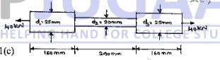
The bar shown in fig. Q1 (C) is tested in a universal testing machine. It is observed that at a load of 40kN the total extension is 0.285mm. Determine the "Young's modulus of the material.
Derive relation between Modulus of Rigidity. Young's modulus and Poisson's ratio.The bar shown in fig.
A steel rod is of 20m long at a temperature of 20°С. Find the free expansion of the bar,when the temperature is raised to 65°C. Also calculate the temperature stress produced for the following cases: i) When the expansion of the rod is prevented ii) When the rod is permitted to expand by 5.8mm. Take =12 x 10°C and E=200 GPa.
A load of 2MN is applied on a column 500mm x 500mm. the column is reinforced with four steel bars of 1 Omm diameter, one in each corner. Find the stresses in the concrete and steel bars. Take E for steel as 2.1 x 10⁵ N/mm and for concrete as 1.4 x 10 N4/mm2.
a. Define :
i) Principal plane
ii) Principal stresses.
Determine the magnitude and direction of resultant stresses on a plane inclined at an angle of 600 to major principal stress plane, when the bar is subjected to principal stresses at a point 200MPa tensile and 100MPa compressive. Also determine the resultant stress and its obliquity.
Two wooden pieces 100mm x 100mm in cross section are glued together along line AB as shown in fig. Q3(c). What maximum axial force 'P' can be applied if the allowable shearing stress along AB is 1.2N/mm2?
Define
i) Bending moment
Define:
ii) Point of contraflexure.
Draw the stress versus strain curve for mild steel specimen subjected to axial tension and indicate the salient points.
Draw the Shear force and Bending moment diagrams for the beam shown in fig. Q4(c).
a. Derive the equation of theory of simple bending with usual notations.
Explain the term:
i) Slope
ii) Deflection
iii) Deflection curve
A simply supported beam 8m long, carries two concentrated loads of 80kN and 60kN at distances of 3m and om from left end support respectively. Calculate slope and deflection under loads. Given E=2.0 105 MPa and I = 300 x 106mm.
State the assumptions made in the theory of Pure Torsion.
b. A hollow shaft of intenal diameter 400mm and external diameter 460mm is required to transmit power at 180rpm. Determine the power it can transmit, if the shear stress is not to exceed 60N/mm2 and the maximum torque exceeds the mean by 30%.
A solid circular shaft is to transmit 250kN at 100 rpm. If the shear stress is not to exceed 75N/mm2, what should be the diameter of the shaft? If this shaft is to be replaced by a hollow one, whose internal diameter is 0.6 times external diameter, determine the size and percentage saving in weight, maximum shear stress being the same.
a. Derive an expression for Euler's crippling load for a column with both ends fixed.
Congratulations! Your trial of
is now active.
Let's catch up on a Zoom call and I'll help you craft a killer career plan! Bring your own coffee.
Sourabh Bajaj


 revolution.
No. of threads per 10 mm = 3,
revolution.
No. of threads per 10 mm = 3,  =12x 10-6 per oC,
  =18.5x 10⁻⁶
per oC, Esteel 200 GPa, Ecopper = 100 GPS.
=18.5x 10⁻⁶
per oC, Esteel 200 GPa, Ecopper = 100 GPS. 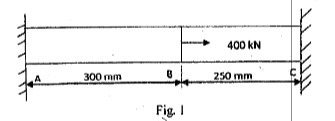
 and E = 2 x 10⁵ N/mm². For
7500
what ratio of L/K, the Euler's formula cease to apply for this column?
and E = 2 x 10⁵ N/mm². For
7500
what ratio of L/K, the Euler's formula cease to apply for this column?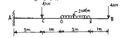
 =12 x 10°C and E=200 GPa.
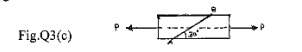

 105 MPa and I = 300 x 106mm.