Forgot Password?
Mobile number is now mandatory for the security of your account.
We've sent you a verification code on your mobile number. Please enter it here to set a new password.
We've sent you a verification code on your mobile number or email address. Please enter it here to set a new password.
Obtain Thevenin's equivalent network of the circuit shown in the following figure and thereby find current through resistor connected between terminals A and B.
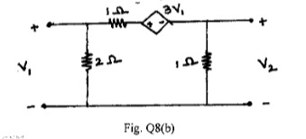
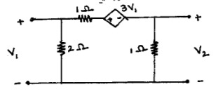
Find Y and Z parameters for the network shown in Fig. Q8
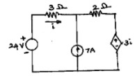
Using source transformation find current through in the circuit shown in the following figure.
Using mesh current method find current through resistor in the circuit shown in the following figure..
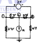
Find all the nodal voltages in the circuit shown in the following figure.
With neat illustrations, distinguish betweeni) Oriented and Non-oriented graphs ii) Connected and un-connected graphs iii) Tree and co-tree.
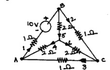
For the network shown in the following figure, draw the oriented graph. By selecting branches 4, 5 and 6 as twigs, write down tie-set schedule. Using this tie-set schedule, find all the branch currents and branch voltages.
State and illustrate superposition theorem.
Using superposition theorem, find value of i in the circuit shown in the following figure..
Show that the power delivered to load, when the load impedance consists of variable resistance and variable reactance is maximum when the load impedance is equal to complex conjugate of source impedance .
Define h and T parameters of a two - port network. Also, derive the expressions for h parameters in terms of parameters.
Find the value of in the circuit shown in the following figure. Verify it using Reciprocity theorem.
With respect to series resonant circuit, define resonant frequency and half power frequencies . Also show that the resonant frequency is equal to the geometric mean of half power frequencies.
A series circuit is energized by a constant voltage and constant frequency supply. Resonance takes place due to variation of inductance and the supply frequency is 300Hz. The capacitance in the circuit is . Determine the value of resistance in the circuit if the quality factor is 5. Also find the value of the inductance at half power frequencies.
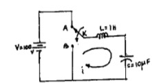
/In the circuit shown in the following figure, the switch K is changed from position A to B t=0. After having reached steady state in position A. Find i, at .
In the circuit shown in the following figure, the switch K is opened at t = 0, Find i, at .
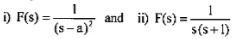
Using convolution theorem find the inverse Laplace transform of following functions..
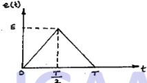
Obtain the Laplace transform of the triangular waveform shown in the following figure.
Define h and T parameters of a two - port network. Also, derive the expressions for h parameters in terms of T parameters.
Fina Y ana z parameters for the network shown in the following figure.
Show that the power delivered to load, when the load impedance consists of variable resistance and variable reactance is maximum when the load impedance(ZL) is equal to complex conjugate of source impedance (Zg)
Using mesh current method find current through 10 resistor in the circuit shown in Fig.Q1 (b)
Find all the nodal voltages in the circuit shown in Fig Q1 (c).
With neat illustrations, distinguish between
i) Oriented and Non-oriented graphs
ii) Connected and un-connected graphs
iii) Tree and co-tree.
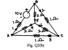
For the network shown in Fig. Q2(b), draw the oriented graph. By selecting braches 4, 5 and 6 as twigs, write down tie-set schedule. Using this tie-set schedule, find all the branch currents and branch voltages.
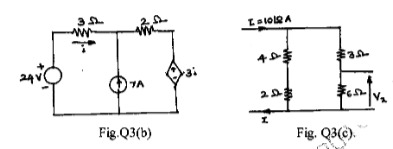
Using superposition theorem, find value of i in the circuit shown in Fig. 03(b).
Find the value of V, in the circuit shown in Fig. 03(c). Verify it using Reciprocity theorem.
Using source transformation find current through R1 in the circuit shown in Fig. Q1(a).
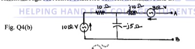
Obtain Thevenin's equivalent network of the circuit shown in Fig. 04(b) and thereby find current through 5 resistor connected between terminals A and B.
With respect to series resonant circuit, define resonant frequency (fr) and half power frequencies (f1 and f2). Also show that the resonant frequency is equal to the geometric mean of half power frequencies .
A series circuit is energlzed by a constant voltage and constant frequency supply. Resonance takes place due to variation of inductance and the supply frequency is 300Hz. The capacitance in the circuit is 10F. Determine the value of resistance in the circuit if the quality factor is 5. Also find the value of the inductance at half power frequencies.
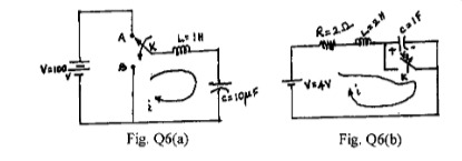
In the circuit shown in Fig. Q6(a), the switch K is changed from position A to B t = 0. After having reached steady state in position A. Find i, and at t = 0
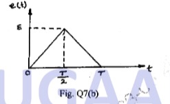
In the circuit shown in Fig. Q6(b) switch K is opened at t = 0. Find i, and at t = 0+
Using convolution theorem find the inverse Laplace transform of following functions.
i) F(s)=
ii) F(s) =
Obtain the Laplace transform of the triangular waveform shown in Fig 07(b).
Congratulations! Your trial of
is now active.
Let's catch up on a Zoom call and I'll help you craft a killer career plan! Bring your own coffee.
Sourabh Bajaj


 resistor connected between terminals A and B.
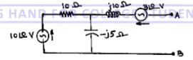
 in the circuit shown in the following figure.
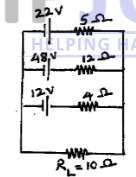
 resistor in the circuit shown in the following figure.
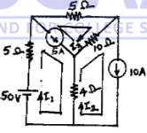 .
.
 .
. is equal to
complex conjugate of source impedance
is equal to
complex conjugate of source impedance  .
. in the circuit shown in the following figure. Verify it using Reciprocity theorem.
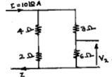
 and half power frequencies
  . Also show that the resonant frequency is equal to the geometric mean
of half power frequencies.
. Also show that the resonant frequency is equal to the geometric mean
of half power frequencies. . Determine the value of resistance in the circuit if the
quality factor is 5. Also find the value of the inductance at half power frequencies.
. Determine the value of resistance in the circuit if the
quality factor is 5. Also find the value of the inductance at half power frequencies. at
at  .
.
 at
at 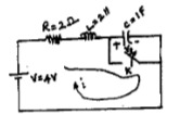
 .
.
 resistor in the circuit shown in Fig.Q1 (b)
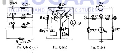
 F. Determine the value of resistance in the circuit if the
quality factor is 5. Also find the value of the inductance at half power frequencies.
F. Determine the value of resistance in the circuit if the
quality factor is 5. Also find the value of the inductance at half power frequencies. and
and  at t = 0
 and
and  at t = 0+