Forgot Password?
Mobile number is now mandatory for the security of your account.
We've sent you a verification code on your mobile number. Please enter it here to set a new password.
We've sent you a verification code on your mobile number or email address. Please enter it here to set a new password.
Draw basic block diagram of a delayed-time-base (DTB) system. Sketch waveform and explain the operation.
Write short notes on LabVIEW.
State important features of LCD displays.
Explain piezo electrical transducer with a circuit diagram.
With a diagram, explain self balancing bolometer bridge.
A displacement transducer with a shaft stroke of 3.0 in. is applied to circuit of Fig.Q7(c).The total resistance of potentiometer is 5 . The applied voltage Vt is 5V when the wiper is 0.9 in. from B, what is the value of output voltage?
State the advantages and limitations of thermistor.
With a neat diagram, explain differential output transducer.
The arms of an ac Maxwell's bridge are arranged as follows:
AB and BC are non-reactive resistors of 100 each, DA a standard variable reactor L1 of resistance 32.7 and CD consists of a standard variable resistor R in series with a coil of unknown impedance Z, balance was found with L1 = 50 mH and Z1 = 1.36 R. Find R and L of coil.
State and derive the two balance conditions for a Wein bridge.
An unbalanced Wheatstone bridge given in Fig.Q6(a). Calculate the current through Galvanometer.
Draw the block diagram of a frequency synthesizer using PLL. Explain its operation.
With a block diagram, explain modern laboratory signal generator.
Explain with examples:
i) Accuracy
With a block diagram, explain construction and working of digital storage oscilloscope.
Describe with a diagram and waveform the operation of a dual trace CRO in ALTERNATE and CHOP Mode.
List the advantages of using negative supply in C.R.O.
Explain C.R.T. features briefly.
With a block schematic, explain the principle and working of dual slope integrating type DVM.
Explain with the help of block diagram the operation of a DFM.
With a neat block diagram, explain the principle and working of successive approximation DVM.
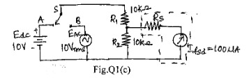
Determine the reading obtained with a de voltmeter in the circuit Fig.Q1(c). When the switch is set to position 'A', then set the switch to position 'B' and determine the reading obtained with a HWR and FWR ac voltmeter.
A component manufacturer constructs certain resistances to be anywhere between 1.14 and 1.26 K and classifies them to be 1.2 resistors. What tolerance should be stated? If the resistance values are specified at 25°C and resistor have a temperature coefficient of +500 ppm/ºc. Calculate the maximum resistance that one of these components might have a at 75°C.
iii) Resolution
ii) Precision
Congratulations! Your trial of
is now active.
Let's catch up on a Zoom call and I'll help you craft a killer career plan! Bring your own coffee.
Sourabh Bajaj


 . The applied voltage Vt is 5V when the wiper
is 0.9 in. from B, what is the value of output voltage?
. The applied voltage Vt is 5V when the wiper
is 0.9 in. from B, what is the value of output voltage?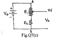
 each, DA a standard variable reactor L1 of
resistance 32.7
each, DA a standard variable reactor L1 of
resistance 32.7  and CD consists of a standard variable resistor R in series with a coil of
unknown impedance Z, balance was found with L1 = 50 mH and Z1 = 1.36 R. Find R and L
of coil.
and CD consists of a standard variable resistor R in series with a coil of
unknown impedance Z, balance was found with L1 = 50 mH and Z1 = 1.36 R. Find R and L
of coil. 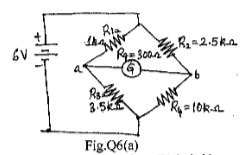
 and 1.26 K
 and classifies them to be 1.2
 resistors. What tolerance should be stated? If
the resistance values are specified at 25°C and resistor have a temperature coefficient of
+500 ppm/ºc. Calculate the maximum resistance that one of these components might have
a
at 75°C.
resistors. What tolerance should be stated? If
the resistance values are specified at 25°C and resistor have a temperature coefficient of
+500 ppm/ºc. Calculate the maximum resistance that one of these components might have
a
at 75°C.