Forgot Password?
Mobile number is now mandatory for the security of your account.
We've sent you a verification code on your mobile number. Please enter it here to set a new password.
We've sent you a verification code on your mobile number or email address. Please enter it here to set a new password.
Distinguish between class A, class B, Class C, class D. class AB amplifiers interms of conduction angle, operating region, application and efficiency.
Explain Op-Amp as peak detector circuit.
Discuss performance parameters of operational amplifiers.
Differentiate ideal Op-Amp and practical Op-Amps.
What are switching regulators? Describe the basic topology of Boost regulator.
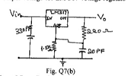
Determine the regulated output voltage for LM 317 voltage regulator shown in Fig. 07(b).
Write a note on 3 terminal voltage regulator.
A step input of amplitude 8 volts is applied to a RC low-pass circuit shown in Fig. Q6(c)(i)and Fig. Q6(c)(ii) below. Determine the output voltage at end of : i) 2m/sec ii) 5m/sec iii) Find upper cut-off frequency fw and rise time to
Explain with a neat connection diagram and waveforms how IC555 timer is used as the astable multivibrator.
Explain Barkhausen criteria with suitable circuit diagrams and essential conditions.
An amplifier has a open-loop voltage gain Av = 1000 100. It is required to have an amplifier whose voltage gain varies by no more than 0.1%.
i) Find the value of feedback factor
ii) Find gain with feedback.
Explain all four feedback topologies with appropriate circuit diagrams.
With the help of common-emitter amplifier configuration, explain the criteria for selection of a suitable operating point and the factors affecting its stability.
Carryout the analysis of a transistor amplifier operating in common emitter fixed bias configuration with suitable derivations.
Explain how the h-parameters are determined by making use of transistor's input and output characteristics.
Write short note on:
ii) Emerging display technologies.
i) Cathode ray tube display
Determine the cut-off wave length for silicon and germanium photodiodes, given that their Bandgap energies are 1.1 ev and 0.72 ev, respectively, at 25°C. How will the cut off wave length change when the operating temperature change form 25°C to 200°C?
What are photodiodes? Explain with VI characteristics.
Fig. Q2(b) shows a circuit using E- MOSFET given that the threshold voltage for the MOSFET is 2 V and = 6 mA for = 5V, determine the volume of the operating point.
Draw and explain the working of D-MOSFET with the help of drain current and transconductance curve. When the voltage is applied to the gate of a P Channel D-MOSFET, does the current flow depleted or enhanced?
Explain the gate triggering characteristics of an SCR.
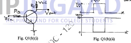
Fig. Q1(b)(i) shows the transistor as an inverting switch with the desired output waveform for the given input waveform as shown in Fig. Q1(b)(ii). Find the value of Vcc ,Rc and RB given that = 80, = 10 mA, the output voltage Vout when the transistor is off is 12 V, VBE = 0.7V.
Congratulations! Your trial of
is now active.
Let's catch up on a Zoom call and I'll help you craft a killer career plan! Bring your own coffee.
Sourabh Bajaj


 100. It is required to have an amplifier whose voltage gain varies by no more than
  0.1%.
0.1%.
 = 6 mA for
  = 5V, determine the volume of the operating point.
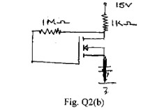
 = 80,
= 80,  = 10 mA, the output voltage V